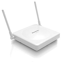
Panasonic KX-TDA50/100/200, KX-TDE100/200, and KX-TAW 2 Channel 2.4 GHz Cell Station (Discontinued)
(Model # KX-T0151)
Note: Picture may not represent the actual product. We are continuously working on improving our website and reserve the right to change specifications, availability, and pricing without prior notice.
Cell Station Unit Features:
- Can handle up to four 7600 multi-cell wireless telephones
- Allows up to two 7600 multi-cell wireless telephones to be used at a time
- Can add up to 128 wireless handsets to the KX-TDA system
- Can add up to 28 wireless handsets to the KX-TAW system
- Also compatible with the KX-TDE100 and KX-TDE200 when connected directly to the extension port of the DHLC and DLC cards
- Supports the KX-TD7684, KX-TD7690, and KX-TD7694 telephones.
Choosing the best site for the Cell Station requires careful planning and testing of essential areas. The best location may not always be convenient for installation. Read the following information before installing the unit.
Characteristics of Radio Waves: The transmission of radio waves and the Cell Station coverage area depend on the structure and materials of the building. Office equipment, such as computers and fax machines, can interfere with radio waves. Such equipment may create noise or interfere with the performance of the PS.
The illustration shows the special transmitting patterns of radio waves.
- Radio waves are reflected by objects such as those made of metal
- Radio waves are diffracted by objects such as metallic columns
- Radio waves penetrate objects such as those made of glass
Relationships Between Radio Waves and Building Structure and Materials
- The Cell Station coverage area is affected more by the building materials and their thickness than the number of obstacles
- Radio waves tend to be reflected or diffracted by conductive objects and rarely penetrate them
- Radio waves tend to penetrate insulated objects and are rarely reflected by them
- Radio waves penetrate thin objects more than thick objects
- The table below shows the transmission tendency of radio waves when they reach objects made from various materials
The example below shows the size of the coverage area of 1 Cell Station if it is installed where there is no obstacle.
Note: Radio signal strength levels are measured during the site survey.
Site Survey Preparation
1. Obtain the map and investigate the installation site.
- Check the obstacles (e.g., shelves, columns, and partitions).
- Check the materials of the structures (e.g., metal, concrete, and plywood).
- Check the layout and dimensions of the room, corridor, etc.
- Write down the above information to the map.
2. Examine the service area demanded by the user on the map, referring to the following example.
- Draw the coverage area around a Cell Station. Extend the coverage area to 30 to 60 meters (98 to 197 feet) in one direction, depending on the materials of the building structures and obstacles in the installation site. Note that a Cell Station cannot be installed outside a building.
- If one Cell Station cannot cover the entire service area, install additional Cell Stations as required. Overlap the coverage areas of adjacent Cell Stations. Where Cell Station coverage areas overlap, the PS will start call handover to the next Cell Station if the signal from one Cell Station becomes weak. However, if a PS moves away from a Cell Station and there are no Cell Stations available for handover, the PS may go out of range and the call could be lost. If the signal from the Cell Station fades, due to the structure of the building, there may be some handover delay. The user will hear a range warning before handover in this case. This also applies in the case of interference from 2.4 GHz apparatus.
Example: Installing in a Room Separated by Walls
-
Things to take note of:
- The room is separated by walls.
- The room is surrounded by concrete walls.
- To see the radio signal strength of more than 1 Cell Station, a Cell Station number must be set for each Cell Station.
- If more than 1 Cell Station is in Radio Signal Test mode, each Cell Station must have a unique number.
Back to Top
Setting and Installing the Cell Station Temporarily for Site Survey
1. Switch the Radio Signal Test switch from OFF to ON.
2. Set the Cell Station number switches as desired.
Note:
3. After setting the DIP switch, connect an AC adapter or battery box to the Cell Station using a power supply adapter. 4. Install the Cell Station temporarily for the site survey. Install the Cell Station at least 2 m (6.6 ft) above the floor, keeping the antennas in the upright position.
Connecting a Cell Station to the PBX
Refer to the following example to connect a Cell Station to the PBX:
Accessory and User-supplied Items for the Cell Station
Accessory (included): Screws × 2, Washers × 2
User-supplied (not included): RJ11 connector
1. Connect the cable from a Hybrid Port or the HLC4card to the Cell Station.
2. Pass the cable through the groove of the Cell Station (in any direction depending on your preference).
